INDEX
■ PID features
It nned to eliminate the offset and make the control response faster. Use PID behavior to satisfy both.
The basics PID control
1) Proportional action ( P action) that outputs a correction amount proportional to the current deviation,
2) Integral action ( I action) that outputs a correction amount proportional to the cumulative value of past deviations,
3) Differential action ( D action) that outputs a correction amount proportional to the magnitude of the tendency whether the predicted value or deviation in the future is increasing or decreasing.
PID is the sum of these three.
This is a characteristic that is exhibited at the time of startup called “dynamic characteristics”.
Furthermore, when a deviation occurs between the target value and the actual value, that is, when a deviation occurs,
4) Proportional action is a “follow-up” action that immediately responds to changes in deviation.
5) The integral operation performs a “ continuous follow-up ” operation in which the control output is continuously output until the deviation becomes zero, that is, until the target value and the actual value are exactly the same.
6) The differential operation is a “follow-up” operation that predicts future movements from the magnitude of the rate of change of deviation and outputs a control output corresponding to this.
In other words, in PID control, control is performed by combining the actions of “immediate follow-up”, “continuous follow-up”, and “foreseeable follow-up” for changes.
This is a characteristic that is exhibited in a stable state called “static characteristics”.
With only three elements, it is possible to perform stable control in two states of “dynamic characteristics” and “static characteristics” from the six aspects of “present / past / future” and “response / continuation / foreseeing”. It has been used in many places even 100 years after it was made.
■ Development of PID
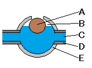
● In ancient Rome, it was necessary to deflate the water pipes for the siphon of the water supply system.
A stone vent valve was used.
If the plug is not filled when the water is full, water will leak from the hole and cause problems such as landslides.
Simple, but it is the origin of ON-OFF control.
Structure of air vent valve
A float
B Air pool
C water
D water pipe
E A valve box with a carved stone
The air mixed into the water pipe lowers the water level and lowers the float, so the air outlet is opened and discharged to the outside.
When the air is low, the water level rises and the float rises, closing the exhaust port
● James Watt
(1736 – 1819 Scottish engineer)
In 1778, a unit called “horsepower” was created as a unit for expressing the output of a steam engine.
For steam engine control, we have developed a valve opening control mechanism by a proportional method using a centrifugal pendulum (flyball).
Fly ball
Flyball structure
● Gapard Clair François Marie Riche de Prony
1755-1839 French mathematician and hydraulic engineer
Dobroni, the inventor of the Prony method of frequency analysis, developed the integral control method in 1791.
● Thrope
(Horatio Nelson Throop 1807-1884 American shipbuilding engineer / captain)
In 1857, we developed proportional differential control for the control of steam engines.
● James Clerk Maxwell
(1831 – 1879, famous for the Scottish theoretical physicist “The Devil of Maxwell”)
In 1868, he published a paper called “On Governor” that clarified the conditions for stable control by conducting a dynamic study of control operation.
“On Governor” cover
● Elmer Ambrose Sperry
(1860-1930) American inventor and entrepreneur
He was known as “the father of modern navigation technology”.
In 1911, we developed a PID controller using a marine gyro compass for automatic steering of ships.
● Foxboro, USA
(Schneider Electric Company since 2014)
In 1912, an ON-OFF controller capable of changing the set value was developed.
● In 1922, Minorsky
(Nicolas Minorsky 1885-1970 American mathematician) published a paper on the PID for automatic steering of ships devised by Sperry.
In 1922, he wrote a paper on PID for automatic steering of ships, devised by Sperry.
● Foxboro, USA
(Schneider Electric Company since 2014)
In 1931, a pneumatic differential PI controller named Stabilog Model 10 was created.
● Taylor Instruments Inc.
(now part of ABB Inc.)
-In 1936, a pneumatic variable PI controller named “Double Response Plus Plus Full Scope” was created. This is said to be the prototype of the PID controller.
A variable PID controller with recording function, named Full Scope 100 in 1939, was created.
